Important formulas for Designing a Substation Grid Earthing System. Magnitude of Fault Current Duration of Fault.

Isolated Foundation Calculation Spreadsheet Foundation Spreadsheet Foundation Engineering
A Earthing Resistance No of Rod for Isolated Earth Pit Without Buried Earthing Strip.
. Cs fault Vin Vout. An overstated fault current can result in an uneconomical substation earth mat design. Of Nigeria and the review of substation practices.
4200 A split factor S. Earth mat design can be done by manual calculations as well as with the help of computer software. Earthing Standards There are a variety of national and international standards available which provide empirical formulae for the calculation of earthing design parameters and shock potential safety limits.
Find the area that the buried earth mat will cover. 1 Calculate Numbers of Pipe Earthing. It is suggested that the use of a high resistivity surface layer is capable of improving the safety while designing substation-earthing grid in high resistivity.
MS excel Spreadsheet to help you find earthing values for substation. It is therefore very important to. Earthmat Design Calculation for BASTA SS Earthmat Design Calculation For KARANGIA SS Considering corrosion factor 5 percent per year for 35 years BASTA 13233 KV SS Rod Functional earthing ie.
And calculation of its technical parameters. Though manual calculation is a good software tools ensure a detailed design so that the earth mat is neither under-designed hence safe nor This paper presents the complete design of earth mat for a 3311kV indoor GIS Gas Insulated Switchgear. In our analysis we have considered an area of 275m x 175m.
Earthing Mat Design For Substation. This calculation is based primarily on the guidelines provided by IEEE STD. Advantageous of Earth mat.
To minimize the danger of high step or touch voltages in critical operating area or places that are frequently used by people 3. Rρ2314xL loge 8xLd-1 Where ρResistivity of Soil Ω Meter LLength of Electrode Meter DDiameter of Electrode Meter. It will have a considerable impact on grid resistance.
In substation earthing system is essential not only to provide the protection to people working or walking in the vicinity of earthed facilities and equipments against the. MOM Box Cable Trench Rack etc are of - 50 Sq mm copper EARTH MAT DESIGN CALCULATION For ANANDAPUR SS ANANDAPUR 13233 KV SS. Determine the line of action of the resultant of all the loads acting on the mat II.
Underground Horizontal Earth Mesh MatGrid The mesh is formed by placing mild steel bars placed in X and Y directions in mesh formation in the soil at a depth of about 05 m below the surface of substation floor in the entire substation area except for the foundations. 115 kV Triple Circuit with Two Shield. This paper presents the design of earthing system forlectrical installations domestic commercial and laboratories etc.
For this purpose a straightforward design based on graphs is proposed. The grounding system in substation is very important. EARTHING GRID DESIGN IS SAFE RESULT 70 kg.
Construction OM and design in substations up to 500 kV. Soil Resistivity Resistivity of Surface Material soil structure and soil model. This paper presents the design of earthing system for 132 KV substations and simulation for calculation of required parameters.
The cross section of the buried cable should calculated in accordance with the value of the phase-to-earth short circuit current but it is common to use the three phase short-circuit current for this purpose. This paper is to provide information pertinent to safe earthing practices in ac substation design and to establish the safe limits of potential difference under normal and fault conditions. 80 2000 Guide for safety in AC substation grounding.
Eduardo has a background in. Systems for th e 13233Kv substation in R ivers st ate. This however is an expensive approach.
The functions of grounding systems or earth mat in include. Choose the configuration of the earth electrode according to the shape of the facility. Complete the design to include all necessary.
F 60 GPR. Check if the calculated resistance meets the design goal. Space saving on the ground level due to substantial reduction of earth pits which.
Common form of a ground mat. For this calculation the following formula must be used. One way of limiting the GPR in high fault current substations is by adding more copper in the earth mat thus reducing the earth impedance.
Read about design of substation earthing system here. ETAP MODEL FOR EARTH MAT DESIGN. Program is designed as per ANSIIEEE 80 Code it calculates step potential of switchyard touch potential of switchyard total length of earthing mat conductor size of earthing mat conductor and total number of earthing rods.
4 22 Most affected parameters for the Earth Mat design are. This paper presents the design of earthing. Earthing Mat Design Calculation Sheet - Free download as Excel Spreadsheet xls xlsx PDF File pdf Text File txt or read online for free.
Provide the ground connection for connecting the neutrals of stat connected transformer winding to earth. With special reference to safety and. If the maximum GPR calculated above does not exceed either of the touch and step voltage limits from Step 5 then the grid design is safe.
Determine the contact pressure distribution as under If the resultant passes through the center of gravity of the. With the incessant increase of power system capacity and voltage grade the safety of grounding grid becomes more and more prominent. Earth mat is preferable for large substations 2.
EARTHING GRID DESIGN IS SAFE otherwise nb 05 otherwise nc 11122158 otherwise nd 05121475 otherwise n 11392371 the corner mesh r or corners ng electrodes OR Lm is the effective buried length for grids with earthing electrodes on the corners and along the perimeter Lm 1558723 ds with earthing. Calculate the resistance to earth for the configuration. The crossings of the horizontal bars in X and Y directions are welded.
Earthing Grid Design Verification Now we just need to verify that the earthing grid design is safe for touch and step potential. Total Length of Eartning Mat Conductor DESIGN OF EARTHING MAT Earthing Conductor Standard Dia of Conductor mm Estimated Length of Earthing Mat Conductor No of Earthing Rod EARTHING MAT DESIGN FOR SUB STATION As per ANSIIEEE Std 80-1986 codeEnter Your Details. The fault current and earth impedance increases.
Ensure safety to personnel in substations against electrical shocks. Earth Mat should be design properly by considering the safe limit of Step Potential Touch Potential and Transfer Potential. He has practiced engineering in the US Canada and Costa Rica.
The Earth Resistance of Single Rod or Pipe electrode is calculated as per BS 7430. Design of uniform mat Design Assumptions mat is infinitely rigid planner soil pressure distribution under mat Design Procedure I. Successful operation of entire building power system depends on efficient and satisfactory performance of well-designed earthing system.

Quantity Surveying Structural Elements Of Buildings Concrete Staircase Building Structures

Pdf A Systematic Method For The Design Of Earthing System For Low Voltage Installations
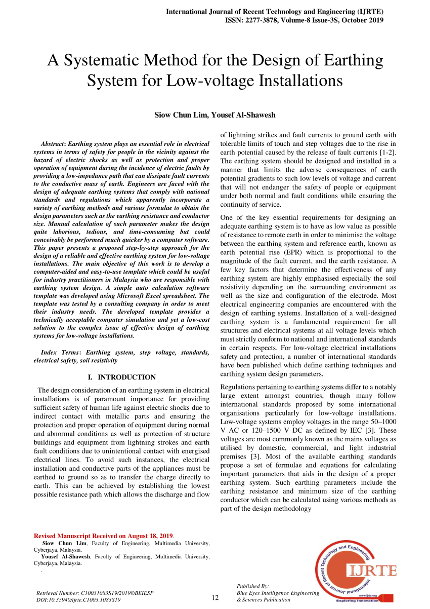
Pdf A Systematic Method For The Design Of Earthing System For Low Voltage Installations
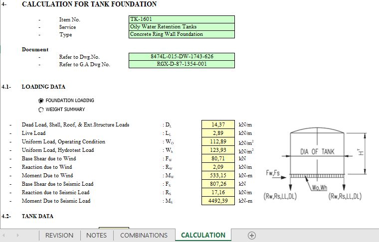
Tank Concrete Ring Wall Foundation Spreadsheet
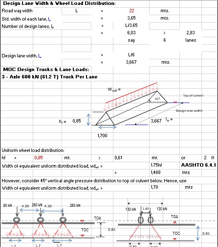
Arch Culvert Design And Calculation Spreadsheet

Fuel Tank Ring Beam Design Calculation Design Guidelines Design Beams

Pdf A Systematic Method For The Design Of Earthing System For Low Voltage Installations
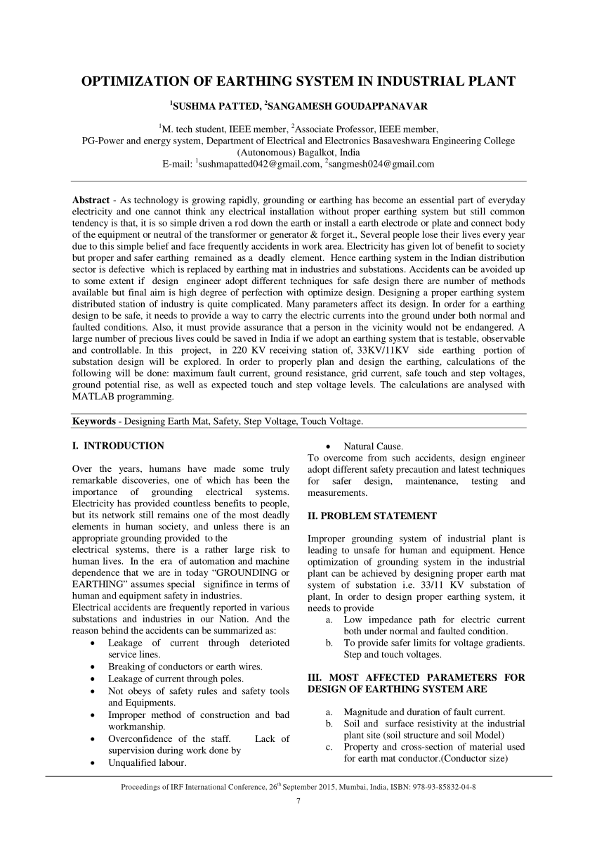
Pdf Optimization Of Earthing System In Industrial Plant
0 komentar
Posting Komentar